Maps Ford
[wpfilebase tag=list id=’696,695,694′ tpl=3-col-maps /]
Unichip Map Label
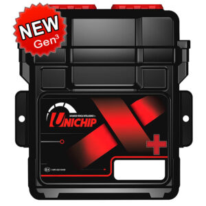
Map Label On The Back Of The Unichip
On the back of the Unichip is a label indicating the 5 mapsMap#1 K&N-Map#2 K&NMap#3 K&N+Map#4 ValetMap#5 ImmobilizerCan you provide any more detail, explanation on these 5 maps
So I wrote a article that explains in detail how the different maps work, below is a short excerpt about the article.
Unichip Map Names – What do they mean?
Each Unichip gets programmed with 1, 2 or 5 different maps, it all depends on what you order with your plug and play kit. Most plug and play kits come with a 2 way map selection switch in which case the Unichip will be pre programmed with 2 maps. If you upgrade to 3 Way, 5 Way map select switch or the NEW Flux² your Unichip will be programmed with 5 maps.
Now the big question is which map is which? To explain this lets go back to the dyno. When the vehicle is tuned for the first time it would be tuned for MAX horse power at full throttle and best fuel economy at part throttle, this should be the optimal map and the best map to use. The map would have optimized fuel and timing tables, on a normal aspirated vehicle. If you have a turbo you can also modify the boost map.
With the Unichip you have the option to program it with 5 maps, typically this would be variations of your optimal map which was created on the dyno.
Lets say in your optimal map that you had to add 5 degrees of timing to get the MAX horsepower and the fuel map had to be leaned out to get the Air to Fuel ratio spot on because the vehicle was running to rich which is typical. Now we just create more maps based on the original map. Each map will still be tested and tuned on the dyno, read more…
Variable Vane Turbo
The turbocharger is an exhaust-driven centrifugal air compressor. Its purpose is to increase power output by supplying compressed air to the engine. The internal components are oil and air cooled. Engine oil is circulated through the housing, which acts as a heat barrier between the “hot” turbine and the “cold” compressor. Bearings are sleeve type and are lubricated by engine oil. Oil is pumped directly from the oil filter base, then circulated to the turbocharger housing and returned to the sump through an oil drain in the turbocharger center housing.
The electronic turbocharger variable vane hydraulic control valve utilizes the powertrain control module (PCM) to control intake manifold pressure. The turbocharger uses a set of moveable vanes in the turbine housing to change the flow of the exhaust gases throughout the turbocharger. These vanes can be positioned to change the angle or direction and the velocity of flow to the turbine wheel, depending upon the conditions in which the engine is operated. As power demands increase, exhaust gas velocity increases in direct relation, as does intake manifold boost pressure. Conversely, as the flow of exhaust gas diminishes, intake manifold boost pressure is also reduced at the same rate.
Vanes mounted around the internal circumference of the turbine housing are connected to a unison ring. The unison ring links all the vanes together and when the unison ring moves, all the vanes move. The unison ring is moved by exposing either side of an actuator piston to pressurized engine oil. Oil flow to the appropriate side of the piston is regulated by the turbocharger variable control valve whose winding is part of a pulse width modulated (PWM) circuit regulated by the PCM. An increase in duty cycle of the PWM circuit will route oil through the turbocharger variable control valve in a way that will cause piston movement that increases manifold pressure (BOOST). Decreasing the pulse width will direct oil such that the manifold pressure (BOOST) will be decreased. Turbocharger control is a closed-loop system using the exhaust pressure (EP) sensor to provide feedback to the PCM. In response to engine speed, engine load, manifold pressure and barometric pressure, the PCM provides a duty cycle to the turbocharger variable control valve to cause it to match manifold pressure (BOOST) to the requirements of the engine.
Expanding exhaust gases drive the turbine shaft assembly to speeds over 100,000 rpm . Filtered air entering the compressing side of the turbocharger is compressed and delivered through a charge air cooler (CAC). The very hot compressed air is cooled, then continues on to fill the intake manifold at a pressure higher than atmospheric pressure. Because considerably more air is forced into the intake manifold, the results are increased power, fuel efficiency and the ability to maintain power at higher altitudes.
Keep Alive Memory (KAM)
Keep Alive Memory (KAM)
The PCM stores information in KAM (a memory integrated circuit chip) about vehicle operating conditions, and then uses this information to compensate for component variability. KAM remains powered when the vehicle key is off so that this information is not lost.
Keep Alive Power (KAPWR)
The PCM stores the vehicle operating conditions in the KAM and uses this information to compensate for component variability. The KAPWR circuit supplies a constant battery voltage (B+) input to the PCM to maintain the memory contents when the key is in the OFF position.
Power Ground (PWR GND)
The PWR GND circuit(s) is directly connected to the battery negative terminal. PWR GND provides a return path for the PCM VPWR circuits.
Reference Voltage (VREF)
VREF is a consistent positive voltage (5.0 volts ±0.5) provided by the PCM. VREF is typically used by 3-wire sensors and some digital input signals.
Signal Return (SIG RTN)
The SIG RTN circuit(s) is a dedicated return path for VREF applied components.
Vehicle Buffered Power (VBPWR)
VBPWR is a regulated voltage supplied by the PCM to vehicle sensors. These sensors require a constant 12 volts for operation and cannot withstand VPWR voltage variations. VBPWR is regulated to VPWR minus 1.5 volts and is also current limited to protect the sensors.
Vehicle Power (VPWR)
VPWR is the primary source of PCM power. VPWR is switched through the PCM power relay and is controlled by the ignition switch. With the key in the START or RUN position, voltage is supplied to the PCM power relay coil. The supplied voltage energizes the relay and closes the internal relay contacts. With the relay contacts closed, VPWR is supplied to the PCM.
FORD 6.0 Liter Diesel
FORD 6.0 Liter Diesel
ELECTRONIC ENGINE CONTROL (EEC) SYSTEM
Overview
The powertrain control module (PCM or ECU) contains both engine and transmission microprocessors. Operating information, as well as concern information, is communicated between the 2 processors through the controller area network (CAN). Both can be programmed individually.
Fuel control is accomplished by the PCM and the fuel injector control module (FICM). The 2 modules communicate operational information through private J1939 CAN communications.
The Ford EEC system provides optimum control of the engine and transmission through the enhanced capability of the PCM. The EEC system also has an on board diagnostics (OBD II) monitoring system with features and functions to meet federal regulations on exhaust emissions.
The EEC system has 2 major divisions: hardware and software. The hardware includes the PCM, FICM, sensors, switches, actuators, solenoids, and interconnecting terminals. The software in the PCM provides the strategy control for outputs (engine and transmission hardware) based on the values of the inputs to the PCM. The software in the FICM provides the strategy control for the fuel injectors based on the values of the outputs from the PCM. The EEC hardware and software are discussed.
The PCM receives information from a variety of sensor and switch inputs. Based on the strategy and calibration stored within the memory chip, the PCM generates the appropriate output. The system is designed to minimize emissions and optimize fuel economy and driveability. The software strategy controls the basic operation of the engine and transmission, provides the OBD strategy, controls the malfunction indicator lamp (MIL), communicates to the scan tool through the data link connector (DLC), allows for flash electrically erasable programmable read only memory (EEPROM), and controls failure mode effects management (FMEM).
ECU Tuning with the Unichip
The modern Multiport Fuel Injection System consists of sensors which detect the engine conditions, the ENGINE CONTROL MODULE (ECM) which controls the system based on signals from these sensors, and actuators which operate under the control of the ECM.
The ECM carries out activities such as fuel injection control, idle air control, and ignition timing control. In addition, the ECM is equipped with several diagnostic test modes which simplify troubleshooting when a problem develops.
The two main variables that you want to control or alter is the timing and fuel
IGNITION TIMING CONTROL
The ignition power transistor located in the ignition primary circuit turns ON and OFF to control the primary current flow to the ignition coil. This controls the ignition timing to provide the optimum ignition timing with respect to the engine operating conditions. The ignition timing is determined by the ECM from engine speed, intake air volume, engine coolant temperature, and atmospheric pressure.
FUEL INJECTION CONTROL
The injector drive times and injection timing are controlled so that the optimum air/fuel mixture is supplied to the engine to correspond to the continually-changing engine operation conditions. A single injector is mounted at the intake port of each cylinder. Fuel is sent under pressure from the fuel tank to the fuel injectors by the fuel pump, with the pressure being regulated by the fuel pressure regulator. The regulated fuel is distributed to each of the injectors. Fuel injection is normally carried out once for each cylinder for every two rotations of the crankshaft. The firing order is 1-3-4-2. Each cylinder has a dedicated fuel injector. This is called multiport. The ECM provides a richer air/fuel mixture by carrying out “open-loop” control when the engine is cold or operating under high load conditions in order to maintain engine performance.In addition, when the engine is under normal operating temperature after warming-up, the ECM controls the air/fuel mixture by using the heated oxygen sensor signal to carry out “closed-loop” control. The closed-loop control achieves the theoretical air/fuel mixture ratio where the catalytic converter can obtain the maximum cleaning performance.
With the Unichip you have full control over these parameters to make changes to the timing and fuel maps. The Unichip has 24 RPM sites between 100 RPM and 24000 RPM and 13 load sites between closed throttle full throttle position. This equates to 312 possible adjustments for each map. In turn the Unichip will interpolate between each load site 16 times which gives you a very high resolution dense map.
UniQ is Unichip’s latest software package for tuning engine’s. This software is a radical shift from classic DOS system which was in operation for over a decade. Take the Unichip software for a test drive and see for yourself.
Purchase Unichip products at wholesale prices or find Unichip Maps for all vehicles
What is Unichip?
The Unichip is a sophisticated, piggy back computer that works in harmony with your vehicle’s factory computer. It electronically resides between your car’s ECU and engine, giving you full control over your vehicle’s engine management system. The Unichip does not alter your vehicle’s factory engine management control unit in any way.

Increased Engine Power
The Unichip delivers torque gain and increased power across the entire RPM range. Power gains up to 13 % is common in normal aspirated vehicles and in turbo vehicles a 30% gain as measured by an accurate chassis dynamo-meter can be expected. It is however difficult to predict exact power gain because it is influenced by the design and condition of the engine and the factory calibration of the engine control unit. That said, the Unichip is far more advanced than “generic plug-in performance chips” and it delivers the most personalised power result every time.
Fuel Economy
Fuel economy is at the top of car manufacturers priority lists these days. However, even in this rat race for best fuel economy the Unichip stands it’s ground. The Unichip will almost always improve fuel economy in vehicles with even the slightest modification such as an aftermarket air intake. This is especially true and more obvious in older and highly modified vehicles. We receive frequent testimonies from customers about increased fuel economy after installing the Unichip.
Works in Harmony with ECU
A major advantage of Unichip is that it works in harmony with the factory ECU to enhance and unleash the best possible performance result without compromising engine durability. Unichip is loaded with an operating system and program which enables it to correctly communicate with your vehicle’s ECU without making physical, electrical, or electronic changes to the factory computer.
Suitable for Most Vehicles
The Unichip is a universally applicable module designed to work in virtually any vehicle. Most EFI cars, whether normally aspirated, turbocharged or supercharged, respond extremely well to Unichip enhancement. It is individually programmable and fully adjustable to cater to exhaust headers, cat back exhaust systems, high flow air cleaners, performance cam shafts, or larger turbochargers and inter coolers.
Free Unichip Tuning Software available. Click here to get your Unichip Software Download today.


