How To… Unichip Turbo Module
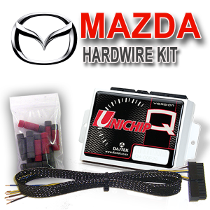
The Unichip Turbo Module
The turbo module is designed for aftermarket turbocharger or supercharger applications.
It is a 3 in 1 unit which are:
- Built-in MAP sensor
- 0-5 Volt Signal Clamp
- Injector or Solenoid
![]()
Click on the images below to enlarge
[singlepic id=21 w=320 h=240 float=left]
[singlepic id=30 w=320 h=240 float=right]
![]()
| Tip: | |
| Warning! Never mount the turbo module inside the passenger compartment, see tip above |
Powering-up the Turbo Module
Lets go into details on each of the features of the Turbo Module. To explain this I will use a block diagram format as shown in the schematic picture below. The second picture shows 12 volt battery voltage connected to pins 6 (12 volt negative) green wire, and pin 3 (12 volt positive) red wire.
![]()
Click on the images below to enlarge
[singlepic id=31 w=320 h=240 float=left]
[singlepic id=34 w=320 h=240 float=right]
![]()
The Map Sensor
The MAP sensor inside the Turbo module will create an output signal from 0 to 5 Volts for an absolute pressure from 0 to 2.5 bar. There is also a 3.5 bar version available. If you only want to use the MAP sensor signal you only have to connect to the Unichip + 12v and Unichip ground. Connect the map sensor signal to the input you will be using to measure the boost. You may use any of the 5 voltage inputs. Typically you will use the TPS or 0-5V 1 input.
![]()
Click on the images below to enlarge
[singlepic id=35 w=320 h=240 float=left]
[singlepic id=36 w=320 h=240 float=right]
![]()
The Signal Clamp
The Turbo module has a signal clamp. The clamp inside the version Q is much better, but if for any reason you want to use the clamp circuit in the turbo module you can still do so. To set the clamp, power the TBM with the thin brown and red wires. Supply the black “signal in” wire with 5 Volts and measure between the “clamped signal out” wire and the thin brown wire with a digital voltage meter. Turn the trim-pot until the desired clamping voltage is reached. A typical value would be 4.5 Volts. If a five volt supply is not available you may power the “signal in” wire straight from the battery. In this case you have to set the clamping value about 0.15 Volts higher than desired clamping voltage. If you aren’t using the clamp simply don’t connect the “signal in” or “signal out” wires.
![]()
Click on the images below to enlarge
[singlepic id=37 w=320 h=240 float=left]
![]()
The Driver
The driver in the Turbo Module is designed to drive devices with impedance between 3 and 16 ohms. Lower impedance will destroy the driver! To use the driver in the Turbo module you have to connect the battery negative, the injector (or other solenoid) pull-down signal, the Unichip power, and Unichip ground.
![]()
Click on the images below to enlarge
[singlepic id=38 w=320 h=240 float=left]
[singlepic id=39 w=320 h=240 float=left]
![]()


